CAUTION:Avoid using Lead solder on Lead Free products bearing this symbol.
NOTE-1: Read this completely first before beginning the project.
NOTE-2: Buzzing may still be present but goes away when you touch the strings because shielding is either not present or is not effectively connected to ground. Please refer to >Technical >Faults & Solutions >Harness Diagnostics page on this Webpage to diagnose and solve your noise/shielding issue.
NOTE-3: The lower pot labelled *Tone* is our Push/Push K9 control that when turned to "0" connects the neck pickup to whatever else is selected by the 5 position switch. This increases the available combinations of the pickups from 5 to 7. (ie bridge + neck & all 3 together)
NOTE-4: With selector switch in position 2 and the Push/Push switch is popped out the Bridge and Middle are connected in series. The neck pickup can be connected in Parallel with the rotary part of the control as in note 2. For full details view my "K9 selection chart" see Support >>Install info >Switching function chart.
NOTE-5: The middle pot is a Master Tone control.
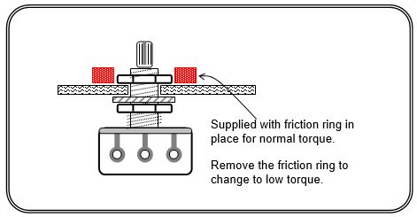
NOTE-6: The volume pot has a bypass filter fitted (see bottom photo). If you feel the sound is too bright when the volume is rolled down the filter can be disconnected simply by cutting or de-soldering the wires that connect from the series Cap/Resistor to the pot terminals.
NOTE 7: The little slide switch on the circuit board selects between two different tone capacitors. The left position selects our High Definition Tone cap while the right position selects a regular (normal) tone cap, as described in the harness section of Products on www.kinman.com
NOTE 7b: The second slide switch swaps from 250k pot load to 500k
NOTE-8: The knobs should be an easy slide fit on the Pot shafts. Open the split shaft with extreme care only if the knob is loose. If excessive force is used one half of the split shaft will break off. Also if the knob fits too tightly it will damage the switch when pulling the knob off.
CAUTION: The knob on the push/push switch should only be removed with the switch in the "OUT" position. Damage caused by pulling the knob off the shaft with the switch in the"IN" position is not covered by warranty.
NOTE-9. Advanced feature: Occasionally a pot or control becomes noisy or fails in use so the pots are "user replaceable" without soldering. The controls connect to the circuit using miniature plugs and sockets. Before re-assembling the guitar make sure all plugs are engaged in their sockets correctly by aligning the coloured dots. On previous side mounted sockets the White wire of the plug attached to the volume pot should be away from the pickguard
Tools needed:
- Smallish/Medium X head screwdriver to remove and replace the pickguard mounting screws.
- Small blade screwdriver to tighten the terminal block connections.
- Razor blade or other small sharp blade to cut plastic insulation on Black ground wire. If you have cloth covered wires you don't need to cut it, just push it back to expose bare wire. (see #2)
- USA Models: 1/2" (or 13mm) tube spanner (or nut driver) to tighten the pots and jack socket.
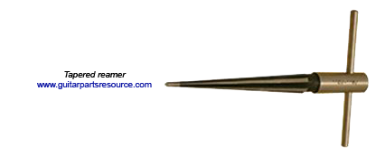
- Non USA models: In addition to above you will need an 11mm tube spanner (or other nut driver) to remove the original pots. The pot holes in the pickguard may have to be enlarged from 5/16" (8mm) to 3/8" (9.5mm) for the Kinman pots by using a 9mm (approximately) diameter round file or preferably using a tapered reamer.
CAUTION: do not drill as it is dangerous to enlarge existing holes in a pickguard using a power drill because the drill will bite into the plastic and spin the pickguard likely causing personal injury.
1) Remove the strings and then the pickguard. Place the pickguard upside down adjacent to the guitar right beside it, close enough so the output socket cable does not pull on it's connections.
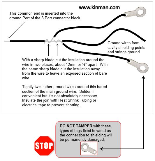
2) Cut or break the ground wire(s) (coming from the spring claw at the rear of the guitar -and/or- from the central ground point, as the case may be) away from the casing of the volume pot by working the wire(s) around and around at the solder point until it breaks. Then cut and strip or push the insulation back about 1/4" (6mm) so it or they are ready to insert into one of the ports of the screw terminal block mounted on the switch module.
3) DO NOT TAMPER with or remove any screw and associated solder tabs like this![]() that are attached to the floor or wall of any cavity. These provide a 'ground' for the conductive coating (Shielding) that is applied to the cavities and doing so will render the Shielding ineffective. If this happens the buzz level will be excessive, and is difficult to fix.
that are attached to the floor or wall of any cavity. These provide a 'ground' for the conductive coating (Shielding) that is applied to the cavities and doing so will render the Shielding ineffective. If this happens the buzz level will be excessive, and is difficult to fix.
4) Remove the Output socket from the recessed steel plate. Cut or break the output socket off the end of it's two wires by working the wires around and around at the solder points until they break.
5) NOTE: Try to keep the original wiring harness in tact as much as possible for possible reuse or resale.
6) De-mount the original pickups and controls from the pickguard and withdraw the wiring harness complete.The pickguard and guitar should now have no remaining connections to the original pickup or controls.
You should now be ready for the Kinman install.
7) Unpack and remove the replacement pickups and wiring harness from the plastic shipping panel. Remove the pots one at a time, replacing the nut as you go to prevent the star washers from coming off the bush. Pickguard models: Unplug and mount the pickup to the pickguard with exactly the same orientation as received on the shipping plate using the Red silicone rubber tubes as springs around the screws. Use the Kinman mounting screws. The pickup with the Blue plug is for neck position (long cable), the White plug is the middle pickup (mid length cable) and the Red plug for bridge position (short cable).
8) Then fit all the controls into the holes and spaces in the pickguard left by the original parts, also mount the output socket on it's recessed holder.
Rear rout control cavity models: Unplug and mount the pickup into their body cavities using the Red silicone rubber tubes as springs around the screws. Do not use the Kinman mounting screws and do not pack foam under the pickups as this can cause severe damage. Refer to No Pickguard install in this section of Install Info. Poke the cables into the connecting tunnel leading to the control cavity.
9) Unplug all controls from switch assembly. One at a time remove and install all the rotary controls into the holes and spaces left by the original parts as shown in Diag 1& 1a below, as well as the output socket on it's recessed holder. Do NOT mount the switch until later.
- NOTE: The Star washer should not be fitted on the outside underneath the nut, but only on the inside between the recessed jack holder and the jack socket itself.
- Make sure the socket is tightened in the position where the *hot* leaf-spring terminal is centred on the recessed jack holder, otherwise it might contact the wall of the cavity and cause a partial short via the wood or shielding resulting is BAD sound. Also this makes the plug difficult to insert. On some copy guitars it may be necessary to enlarge the cavity to avoid the short mentioned above.
- If the pot holes are too small see *Tools needed >Non USA models* at top of page.
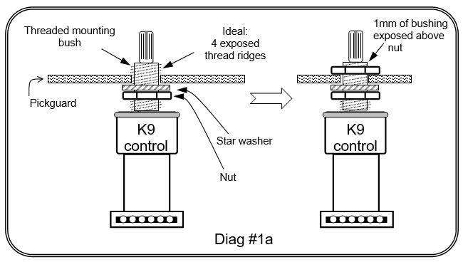
10) Check the Volume and Tone pot bushings to ensure there are at least 4 thread ridges exposed above the pickguard. If too little thread form is available for the nut it is advisable to adjust the second nut below the pickguard to allow sufficient grip of the fixing nut. But be aware that excessively exposed thread-form results in the skirt of the knobs being too far from the pickguard. Expect a gap between knob and pickguard of about 2+mm.
Mount the pots
Changing the Torque of the volume pot
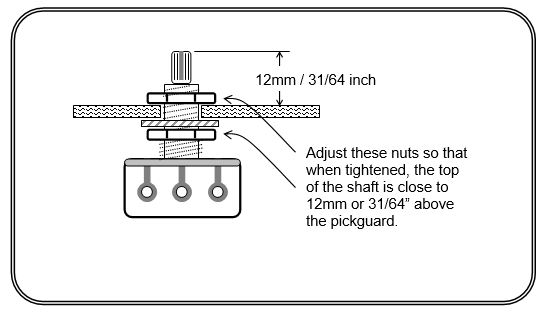
Mounting the K9 Control correctly
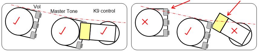
12) Lightly tighten the pot nuts, then adjust the rotational position of the pots and tighten the nuts firmly so the terminal pads are as shown in the diagram #2 below. If they poke out they might cause a short circuit by contacting any shielding on the cavity wall. Tighten firmly with a 1/2" (13mm) tube spanner (do not tighten excessively).
Aligning the pots. Diag #2
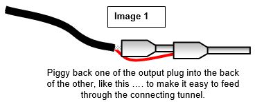
13) Mount the recessed jack plate and poke the cable through the connecting tunnel into the main control cavity and screw the jack holder to the guitar. The two plugs on the cable should be piggy backed, one inside the back of the other, as depicted in photo 1 below. This arrangement makes it easier to thread them through the connecting tunnel.
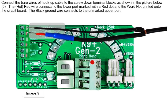
14) Before mounting the switch: undo the 3 screws to open the Connector Block ports 3 or 4 turns and insert the two plugs and ground wire(s) into their respective ports as shown in image 2 below. The red wire is plugged into the upper terminal that has the red dot (same with Left hand harness). The Shield is plugged into the middle terminal and the black bridge grounding wire/s (from the spring claw at the back of the guitar -and/or- the central ground point, as the case may be) into the remaining lower terminal. Tighten the screws firmly but not too tightly.
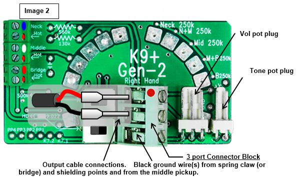
NOTE about existing ground wiring: We do not advocate Star grounding in passive guitars as desirable, in fact it can cause headaches but don't change it if that's how it is. With that in mind all shielding and ground wires (usually Black) should be somehow connected (either directly or indirectly) to the lower port of the Connector block. This included the control cavity shielding (if present), output cavity shielding (if present), and the strings - direct from the bridge as in the case of hardtails or via the spring claw on vibrato models. If there are 2 or less individual grounding wires insert them into the lower port of the connector-block. If there are 3 or more separate wires all these wires can be (and usually are already) connected together at another point and a single wire leading from that point can be terminated into the lower port of the connector-block (image 3 below refers). Failure to ground any shielding will result in unwanted noise. Please navigate to >Technical >Faults & Solutions > Harness Diagnostics to solve your noise/shielding issues.
15) Mount the switch (module) and tighten the screws.
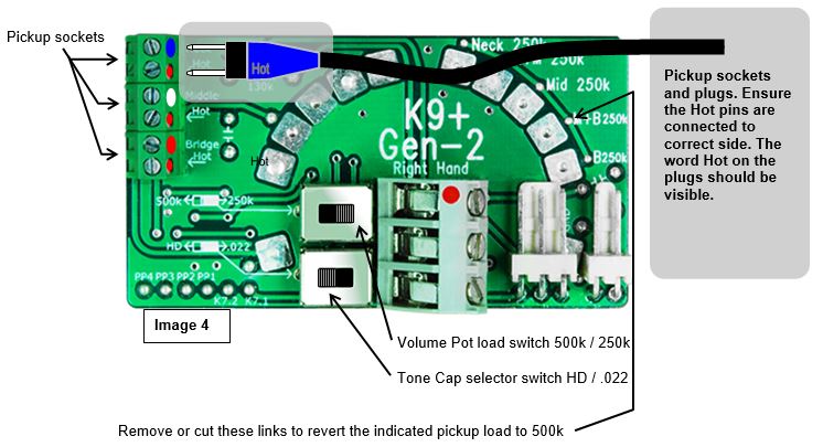
16) Insert the pickup plugs into their respective sockets as shown in image 4 below. Red is bridge pickup and is the bottom plug. White is the middle pickup in the middle and Blue is the neck pickup at the top. Make sure the 'Hot' pins go into the correct holes (the bottom one in the photo). Push the plugs all the way into the sockets. Arrange the cables for neatness and tighten the cable tie. The word HOT should be visible on the outside of the plugs. For added security apply a small section of adhesive tape over the plug and socket to prevent unwanted dis-engagement (although this is highly unlikely as the cables are confined).
17) Humbucker coil splitting connections into a K9 go to Image 5b on page 8 page
18) CAUTION: AVOID bending the sockets away from the circuit board, i.e. don't strain these cables on the plug.
19) Tighten the switch mounting screws. Connect the K9 plug to the K9 control; connect the Tone and Volume plugs to the switch assembly (as indicated in image 3 above) and arrange the twisted black/white wires so they will not get between the cavity floor and the terminal block after install into the guitar.
20) Assemble the pickguard to body taking care not to cross thread the screws in the wood, and proceed to restring and adjust the pickup heights... Please refer to >Support >Adjust & Set-up ... for detailed info on how to get the best out of your pickups and guitar. There is a wealth of information in this section of my Website that will fascinate and delight you for many hours.
21) For anything not right go to www.kinman.com>Tech Support >Faults & Solutions > Harness Diagnostics.
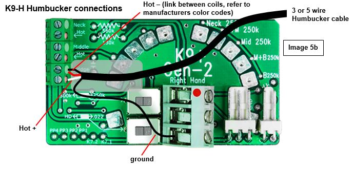
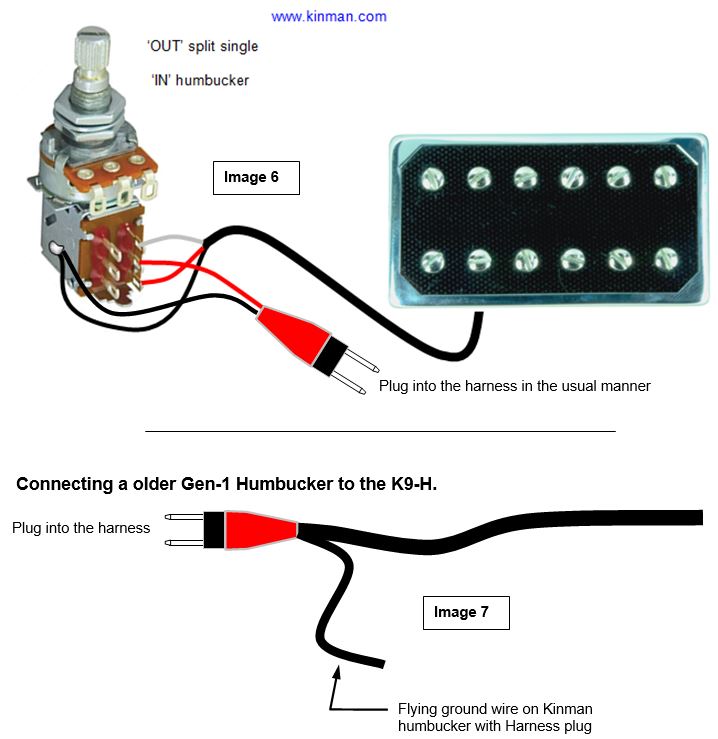
Connecting a splittable Humbucker to a K9-H