Install Guide for P-90 Hx
Original Oct-09 Rev-10 Jan-20
with Soap-bar & Dog-Ear covers into solid guitars with rear routed control cavity.
Les Paul's, LP Jnr's, SG's, PRS etc
Fore-notes and Cautions:
- The P-90 Hx likes a 500k volume pot to maximize dynamic range, touch sensitivity, output level and frequency response. They will work with a 250k pot but the above performances will be somewhat compromised.
- Any P-90 Hx ordered with 3 conductor hook-up cable to easily facilitate reversing the output polarity (phase), when reversed, there will be a little bit more buzzing (RF buzz, not mains hum) than normal when the player is not in contact with the strings acting as a grounded human buzz shield. Any P-90 worth it's salt exhibits the same characteristic, it comes about because of the large surface area of the string sensing coil.
- The four silicon rubber tube springs provided must be cut to suitable length with scissors according to the cavity depth. Details later.

- Mounting under Dog-Ear covers on solid body guitars is explained on page 9 of this guide.
- Do not adjust the preset pole pieces until the end of the install procedure. Avoid excessive adjusting of the pole screws to maintain the torque required to turn them. If they become too easily turned heat them with a hair dryer for about 1 minute. The heat melts the wax in the screw threads and the original torque is restored. Or, remove them and dip the threads into molten candle wax for approx 10 seconds. When reinserted the wax provides desirable resistance to turning. To avoid getting wax on the cover apply some masking tape over the holes (one by one in turn), punch a hole with diameter of the screw's head into the tape beforehand and position it over the hole in the cover while reinserting the screw. When the screw is in desired adjustment position carefully and slowly remove the tape, any excess wax will travel with the tape.
- Avoid cutting the Kinman hook-up cables to save the effort of preparing new ends.
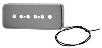
- Gibson Soapbar replacement: If the pickups being replaced are genuine Gibson soapbar’s it best to swap the Gibson covers onto the P-90 Hx as the Kinman covers will be a tight fit in the corners of an original Gibson pickup cavity. The covers will slip off and on easily. If necessary the Kinman covers will squeeze into Gibson cavities but we want to avoid possible chipping of the paint. I am just being cautious here and have installed Kinman covers carefully into Gibson guitars on many occasions without damaging the finish.
- Changing covers: Covers are held firmly on the pickup but slip off easily when pulled. Hold the cover at the ends between thumb and fingers of one hand and the lower part of the pickup between the ends with thumb and fingers of the other hand and carefully separate the two. Take care not to skew the cover, try to keep it parallel to the pickup. When putting the cover back on insert the pickup into the cover 'cable end first' to avoid disturbing the cable entry, and then slide the other half in and press until seated.
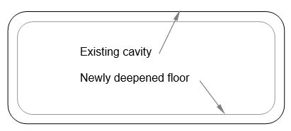
- Pickup cavity concerns: As explained in the *Install Requirements* PDF on the P-90 Hx product webpage the pickup cavity must be deep enough to provide sufficient scope for vertical adjustment. Guitars that already have P-100’s or other stacked hum canceling pickups of another brand installed will likely accept the Kinman P-90 Hx too, without modification. If not the floor of the cavity might need to be deepened on a milling machine for controlled and safe cutting -or- with a router using great care, expertise and experience. To preserve the paint on the walls of the cavity confine the cutting operation to within 2 or 3mm from the walls to avoid scraping the four edges of the cavity with the cutting tool.
- See next page for requirements of pickup cavity depth.
Requirements for pickup cavity depth.
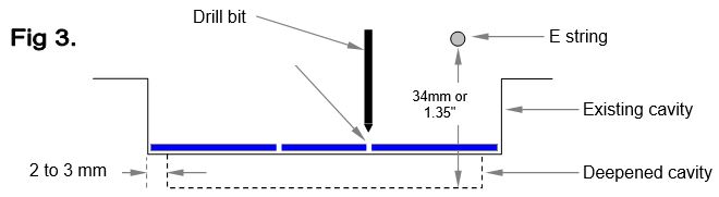
To provide sufficient adjustment ideally there should be 34mm (or 1.35" which is just over 1-1/4") between the bottom of the strings and the bottom of the cavity (measured in the middle of the cavity under the low E string). Refer to Fig 1.
Thin body guitars like the Gibson SG are only 38mm (1.5") thick so the tips of the screws will come to within 5mm of the back of the guitar. Be careful when drilling the holes, use a depth guide on the drill bit.
Gibson P-100 routs require Silicon Rubber tubes 13mm long for neck pickup and 7mm long for bridge pickup (included with pickup). Refer to Paragraph on page 5 - Installing your new pickups.
11. Deepening the pickup cavity with controlled cutting
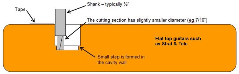
a) Strat’s, Tele’s etc. Remove all hardware and the neck from the guitar. To avoid the base of a hand router scratching the face of the guitar stick sections of a thick tape such as Plumbers Tape or Gaffa Tape to the face of the guitar. To avoid scraping the paint off the cavity walls use a router bit that has a bigger diameter shank then the cutting section. Set the shank so it rubs against the cavity wall and guides the cutter to rout a neatly formed deepening that is a bit smaller then the original rout (as shown in the illustration below).
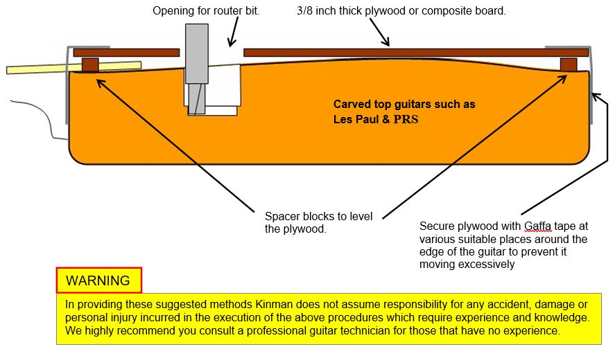
b) Carved tops such as Les Paul, PRS etc. Since the neck’s of this type of guitar are invariably glued into the body it is necessary to raise the router base above the neck by placing a suitable piece of 3/8 inch thick plywood or composite board on top of the guitar, steady it with blocks attached on it’s underside which rest on the face of the guitar. A suitable opening (same shape as but slightly bigger than the pickup cavity) must be cut in this spacer board so allow visual inspection of the cavity and space for the router bit to operate.
12. Drilling screw holes in a virgin cavity floor. Great for project guitars with no holes drilled or after the cavity has been deepened, included in the pack you will find a handy 'drill guide template' that makes it easy to drill the holes for the mounting screws in the correct position. Place it on the floor of the cavity as illustrated. Refer to Fig 1 above. Calculate how deep the hole should be. To avoid drilling through the back of the guitar wrap some masking tape around the drill as a depth guide. Drill a 1.6mm (1/16th") hole into the floor and stop when the masking tape contacts the floor. Keep the drill perpendicular to the cavity floor.
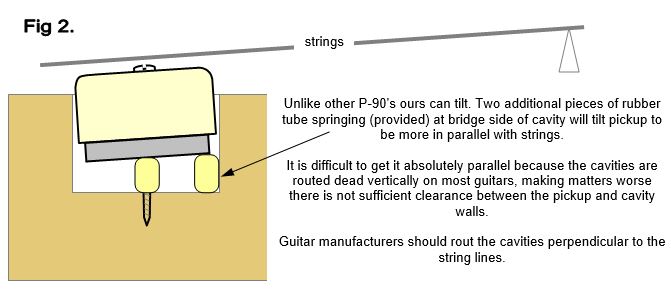
It is preferable to align the template to the side of the cavity closest the bridge, this will help in getting the pickup to sit more parallel to the strings. Refer to Fig 3.
13. Getting the pickup more in parallel to the strings. It is desirable for the pickup to sit close to parallel with the strings, both for the sake of appearances and performance. Unfortunately most guitar makers rout the cavity perpendicular to the back of the guitar, not to the string line. The Kinman P-90 Hx has been designed to tilt by using 2 little section of (provided) silicon rubber tube positioned under the edge of the pickup closest the bridge, this causes the pickup to tilt away from the bridge, allowing a little bit of improvement in parallel-icity. Refer to Fig 2 previous page.
Preparation before install:
Rest your guitar on a bench top with 3 layers of towel or blanket to avoid scratches. Position a block of cork or another suitable (soft) material under the neck around the 5th to 7th fret area to lift the headstock off the bench -or- arrange for the headstock to protrude over the edge of the bench making sure the edge is covered with 3 layers of soft toweling to avoid damaging the finish on the neck.
Remove strings, completely. Also remove the bridge and tailpiece if they are not secure. SUGGESTION: Draw the existing wiring onto the last page (9) of this document.
Remove the old pickups by de-soldering their wires from the pots. First refer to: CAUTIONARY SOLDERING TIP on the next page.
Installing your new pickups.
Mounting screws: Unpack the new pickups, insert the 2 long mounting screws (provided) through the 2 small holes in the top of the cover. In the case of Gibsons', with the solid metal inserts embedded in the wood that receive the mounting screws, use the original Gibson screws as these have fine threads designed for solid metal. The screws provided with the pickups have a coarse thread which is designed for wood. Push the silicon rubber tube springs over the ends of the screws that protrude out the other side, these springs will be easily retained there. You will also notice the pickup has no tendency to fall out of the cover, this will make the install far easier and reduce the risk of accidentally dropping the pickup onto the guitar.
Neck pickup: Begin with the neck pickup and feed the cable into the wiring tunnel. This is more easily accomplished by first poking a length of 1mm solder through the tunnel right into the control cavity, then hooking the solder to the end of the pickup cable and pulling the cable into the tunnel from the control cavity end until the pickup is almost in. Turn the guitar onto it's side for access from both front and back for the cable pulling part of this operation, and recruit assistance from some else as this can be a task better suited to an octopus.
Note: The P-90 Hx should ideally be oriented with the cable exit from the pickup being closest to the entry to the wiring tunnel. Should the cover be printed with a Logo the cover can easily be removed and re-oriented so the logo is the right way up with the guitar is standing up.
Lay the guitar onto it's back again, make sure the excess cable doesn't scratch the back of the instrument. Pull the pickup by it's cable, from the control cavity, into it's cavity. Avoid laying the cable sideways across the floor of the cavity by aligning the cable end of the pickup with the entrance to the tunnel to prevent damage by the mounting screws. This might require reversing the cover to maintain correct orientation of the logo.
Push down onto the pickup keeping the top surface parallel with the cavity floor, simultaneously advancing the screws (one by one, a little at a time) into the screw sockets in the floor of the cavity. The screws should be relatively easy to turn, if you feel too much force is require back the screws out and start over as they might have missed the socket and be trying to make a new hole into the virgin floor. Stop after a few turns.
Push the pickup down onto the tube springs lightly with your fingers. The top surface should be approx level with the string line when they are fretted at the 14th fret. If higher than you must cut the tube springs to allow this condition to be met. This allows proper adjustment.
This is optional: Remove the pickup from the cavity and cut the additional silicon rubber tube springs same length as the other ones and stand them vertically on the floor in the middle of the cavity, aligned against the edge of the cavity closest the bridge, refer to Fig 2 above. Secure in place with a little bit of BluTak or other like adhesive material. Put the pickup back into the cavity and turn the mounting screws until the pickup is in approximate working position (3mm distance from strings fretted at the 14th). The additional tube springs are intended to cause a slight tilt of the pickup so that the top surface is more towards parallel with the strings.
Bridge pickup: Repeat the operation (above 3 paragraphs) for the bridge pickup. It is possible to crack the cover with excessive screw force so it might be necessary to shorten the silicon rubber tube springs in order to avoid excessive force exerted by the 2 adjustment screws onto the cover on some guitars.
Chrome plated soapbar covers need to be connected to a ground by the attached Black wire. Be careful not to tug on the ground wire with any kind of force as this might break it’s connection with the cover.
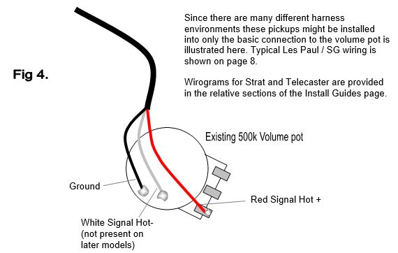
Soldering the connections: Do not remove or change existing original wiring. To solder the connections position the guitar face down on the bench top. Arrange the cables in a neat orderly fashion, avoid cutting them shorter. It is best to remove any existing solder from the 'hot' leg of the pot (it's the outer leg opposite the leg that is soldered to the case of the pot) in order to expose the hole in the top of the leg. Poke the Red wire or ferrule into the hole. Position the cable to prevent the ferrule dislodging then apply a drop of solder to the terminal leg. Hold the iron in contact for about 2 seconds to allow a good solid connection to form. Ensure the wire does not move about while the solder is cooling.
If you ordered with 3 conductor hook-up cable and you need opposite output polarity (phase) to match other pickups then swap the Red and White connections. Disregard the White if you have 2 conductor hook-up cable since no phase reversing is possible.
CAUTIONARY SOLDERING TIP: when soldering pot terminals do so with minimum of time to avoid excessive heat traveling to the pot track (which can be damaged by prolonged exposure to excessive heat).
Poorly done soldering can cause bad sound, no sound, excessive buzzing (RF noise) and loss of tone so read 'Soldering Tips' in the Install Guides section of this website.
Do not replace the rear access cover until the soldering has been proven to work satisfactorily.
Completing the install.
Install a new set of string into the tailpiece before replacing it to the guitar. Turn the guitar over and replace the bridge and tailpiece. Temporarily tape the tailpiece in position to prevent it falling onto the guitar. One at a time tug the strings to seat then securely into the tailpiece and pull them through the holes in the shafts of the tuners. Pull tight then retract the string approximately the same distance that separates the tuner shafts. Kink the string around the edge of the hole and commence winding the string around the shaft, keeping tension applied to the string with one hand. Wind until there is a light tension on the string, this allows easy positioning onto the bridge saddles and nut grooves. Finish by tuning to pitch then stretch the strings by stretching the string sideways at the 12th fret area several times (stretch about 25 to 30mm), retune to desired pitch. Check the intonation of strings at the 12th fret and adjust the position of the bridge as necessary.
A good starting point is to adjust the bass side of the bridge pickup so there is a gap of approximately 2mm between the pole and the underside the E 6th wound string. Adjust the treble side for a 2.5 ~ 3mm gap. The pickup will seesaw somewhat because of the position of the adjusting screws (towards the middle of the pickup) so re-adjust the bass and treble screws several times until the desired gap is established on both sides.
The neck pickup can be similarly adjusted but with gaps of 2.5mm bass side and 3 mm treble side.
On each pickup adjust the poles that are under the plain (non-wound) strings into the pickup until they seat gently. Adjust UP later if required to achieve good string loudness balance. Plug into your favorite amp but before you cut loose contain your excitement for a few moments (it'll be well worth it) and select the bridge pickup and play a slow succession of notes running across the fretboard from low string to high string. The notes should all have same output level, if that's not the case adjust the screw poles to achieve a good balance. Repeat for neck pickup. Players often overlook this step but I assure you that spending a little time to do this properly will reward you with superb sound.
Adjust the output of the neck pickup to be balanced with the bridge pickups by using the height adjusting screws, as described previously.
If all works as it should replace the rear access cover, take care not to over-tighten the screws and possibly split the plastic.
This is not the end of the adjustment phase, all Kinman pickups are very sensitive to adjustment and the P-90 Hx is no exception. I encourage to experiment with the screw poles and see what happens for there will be hidden delights awaiting you there. For example if you want more focus and greater concentration of mid-tones in the sound try adjusting the screws out and adjusting the pickup the same distance down – more or less. You will find there are numerous combinations that yield subtle changes in tonal texture and perhaps you’ll find a sweeter spot, one that hits your spot perfectly.
Never underestimate the impact amplifier controls and outboard effects can have on the sound of a pickup too. Before you begin it's a good idea to start with a clean slate. Don't try to adjust your new Kinman pickups using your previous amp Eq and Fx settings. I suggest you set the tone controls to 12 o'clock (position 5 on the knobs) and dial the adjustments in from there, adjusting the Eq controls only after you get the best result from the pickups. The amp controls will then just fine tune the basic correct pickup adjustments. Don't be afraid to use the controls, that's what they are there for. If your sound needs more or less brightness simply turn the treble control up or down. Same for Mids and Bass.
The moment you’ve waited for:
Now let loose and be inspired …. I wish you a heck of a lot of fun, stimulation, enjoyment and satisfaction exploring your new sonic horizons. Don’t forget to take it soft n slow sometimes as you will discover the many wonderful sonic nuances the P-90 Hx has to offer. Tell me about your experiences using your >Members Area >Message Bank >Compose New Message … type subject line>>> P-90 Hx sonic horizons.
Looking forward to your feedback.
Best wishes …. Chris Kinman.
Mounting under Dog-ears in solid body guitars next page.
Dog-Ear cover mounting:
The P-90 Hx is very versatile and can be mounted under Dog-Ear covers as well as Soapbar covers. You will notice the P-90 Hx does not have extensions for mounting under Dog-Ear covers like original Dog-Ear P-90's do.
Since there are many variations of Dog-Ear covers it is best to use your original covers since they will probably suit your guitar better than replacements.
This method uses a block of high density foam cushioning positioned under the pickup to push it up to the cover and keep it in firm contact. Once positioned under the cover the pick self aligns perfectly to the cover, probably better than P-90's with mounting ears. The pole screws prevent the pickup from skewing inside the cover.
Caution: The foam should not be excessively strong as some covers will possibly distort or develop a crack with excessive constant force applied.
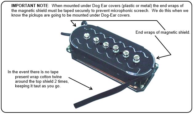
The pickup sits inside the Dog-Ear cover and the medium density (not too soft) foam cushion pushes it into the cover and keeps it firmly in place.